
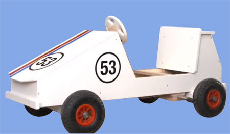
Make a DIY soapbox car
Use your DIY skills to make a soapbox car for your little boy. What it lacks in horsepower, it more than makes up for in passion: the soapbox car will excite little race-drivers.
Beginner DIY-ers should schedule 2 days for this project, while DIY experts will manage it in one. The construction guide is designed for 24mm, 18mm and 9mm plywood. Have the plywood cut to size at your local Builders Warehouse. If you use other materials or thicknesses, modify the plan accordingly.
YOU WILL NEED:
Download the construction guide with a detailed material list and construction drawing here.
Plywood
Perspex
Metal rods, wheels, shaft collars
Rubber hose
Screws, carriage bolts, washers, nuts, ring nuts
Wire cable, wire cable clamps, return springs, spacer rings, carabiners
TOOLS
Jigsaw
Hand-held circular saw
Sander
Cordless drill
Cordless screwdriver
Router with radius bit (5 mm) if available
Material
HERE'S HOW:
Assembling the base tray from the base plate and frame strips
First prepare the base plate. When doing so, observe the dimensions specified in the construction drawing. Use the pencil to mark the cutouts for the control cables and then saw them out with the jigsaw. Before sawing, pre-drill the four corners with the 10-mm drill bit. This will make it easier to manoeuvre the saw blade around the corners. N
ow mark the holes where the brake rods and the steering axle will later be fitted. The two holes for the brake rods each need a recess for the screw heads on what will later be the inside of the base plate. For this reason, first use the 30-mm Forstner drill bit to drill 5 mm deep at the corresponding positions in the plate. Then drill two 8-mm-diameter holes at the same position for the brake rods and a 10-mm hole at the front centre for the steering axle.
Once you have marked the position of the rear axle on the bottom of the base plate, mount the longitudinal and transverse frames with the base plate to form a tray. To do so, pre-drill the base plate with 4 mm diameter and fix the base tray with 18 wood flat head screws (3.5 x 50 mm).
Bottom of the tray
Now screw the strip for the steering stop as specified in the construction drawing with 3.5-x-30-mm screws on the bottom of the base plate. To ensure that the steering axle glides better, you also fit two acrylic glass plates to it as a glide layer. When doing so, make sure that the heads of the flat head screws (3.5 x 35 mm) completely disappear into the plates. Pre-drill the two fixing strips using the 6-mm drill bit and mount a ring nut with a carriage bolt (6 x 50 mm) on each strip. The control cables for the steering and the brakes will later be fed through the ring nuts. Now mount the fixing strips with wood screws (3.5 x 30 mm) on the bottom of the base plate.
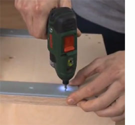
Tip for screwing together two wooden parts
IIn the piece where you want to insert the screws first, always pre-drill a hole that is 0.5 to 1 mm larger than the screw diameter; the hole should be countersunk deep enough for the screw head to completely disappear into it. In the piece that you are going to drill second, pre-drill a hole that is always 1 mm smaller than the screw diameter. This ensures that the screw thread will still grip well.
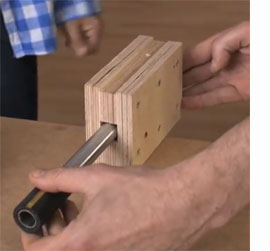
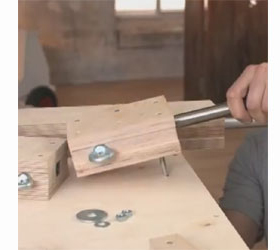
Making the wheel axles and brake rods
The wheel axles and the steering rods each consist of four wooden strips surrounding a metal rod: a support strip, two spacer strips and a fixing strip. To enable the soapbox car to be steered, the front axle is, of course, movable. It will later be controlled using a control cable.
The two brake rods are also fitted as movable parts. The rear wheel axle is, on the other hand, rigid. Drill two 6-mm-diameter holes, each 35 mm in from the edge, into the front axle’s spacer strip. Fit the two ring nuts for the control cable in these holes, each with a carriage bolt (6 x 50 mm).
To enable you to later mount the front axle as a movable part on the base plate, drill a 10-mm-diameter hole for the carriage bolt (10 x 60 mm) in the middle of the support strip. The head of the carriage bolt must disappear into it completely. For this reason, use the 30-mm Forstner drill bit to drill an approx. 5 mm deep countersink. The front and rear axles are assembled in the same way: line up the metal rod in the middle of the support strip and position the spacer strips on the right and left of it without leaving any space. Then put the fixing strip on top and screw together the strips on both sides from above (don’t forget to pre-drill). To make sure that the metal rod cannot slip, drill a 4.5-mm-diameter hole through the middle of the wood into the metal rod. Then insert a screw (4 x 25 mm) to lock it.
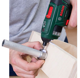
The two brake rods are built according to the same principle as the wheel axles. Since the brake rods are movable like the steering axle, you again fit ring nuts for the control cables here and drill the holes for the subsequent movable attachment to the base plate with the carriage bolt (8 x 90 mm). Don’t forget to fix the two metal rods with a screw, so that they do not slip out of the wooden blocks. To make sure that the brakes work really well, a piece of rubber hose is put on each metal end.
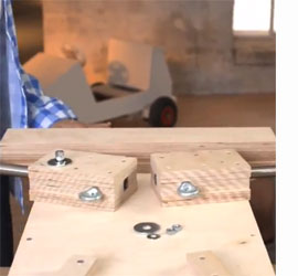
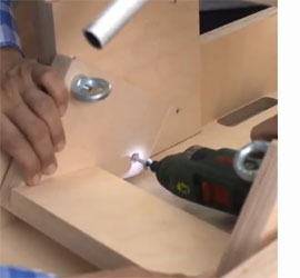
Mounting the wheel axles and brake rods on the base tray
The rear axle is fitted to the base plate by screwing it from the inside of the base tray with 4 screws (5 x 60 mm). To fit the wheel axle and the brake rods, place the base tray on the worktop with the base facing up. The steering axle is connected to the base plate as a movable part by a carriage bolt.
Insert bolt through steering axle, put the two washers on and feed the bolt through the pre-drilled hole in the base plate. Put another washer on the inside of the base plate and fix the bolt with two lock nuts. Similar to the steering axle, the two brake rods are fitted to the bottom as movable parts each with a carriage bolt (8 x 90 mm), each with a washer and two lock nuts. The heads of the carriage bolts are countersunk in the pre-drilled recesses in the base plate. This will enable you to later place the seat there without any problems.
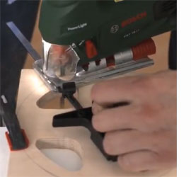
Cutting the steering wheel into shape
Mark the contour of the steering wheel on the panel with the compass: first the outer circle with 200 mm diameter, then the inner one with 170 mm.
Mark the triangles for the cutouts. To make it easier for you to saw these out with the jigsaw, drill 10-mm-diameter holes beforehand at the inner corners. To do so, use G-clamps to fix the panel on a scrap panel that you can drill into. Also pre-drill four holes (4 mm diameter) through which you will later fit the steering wheel to the steering wheel fixing. To saw the cutouts, it is best to use a thin curve-cutting saw blade.
To saw the circular contour of the steering wheel, set the radius on the guide rail and fix it as a compass with a pin in the centre. Finally, chamfer all edges and sand them smooth. Alternatively, you can use a router to cleanly rout out the steering wheel and round off the edges with a 5-mm radius bit.
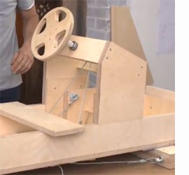
Making the steering unit and fitting the steering wheel
Mark the two side sections of the steering unit as specified in the construction plan and cut out with the jigsaw. Drill an off-centre 6mm-diameter hole in each of the two side sections to attach the ring nut with the carriage bolt (6 x 40 mm); fit them.
The steering cable will later be fed through the ring nuts. In each of the transverse strips of the steering unit, drill a 20mm hole in the middle for the steering axle.
Mount the side sections and the transverse strips with screws (3.5 x 50 mm). You also drill a 20mm-diameter hole in the middle of the steering wheel fixing. You drill a 4-mm-diameter hole on one side for the lock. Now put the fixing on the steering rod, pre-drill with the 3-mm drill bit and lock the steering wheel fixing with a screw (3 x 60 mm). Then screw the steering wheel onto the fixing with four screws (3.5 x 40 mm).
The steering rod is inserted into the corresponding holes of the steering unit and aligned with shaft collars and set screws. To make sure that the steering cable does not slip later on, slit open a piece of rubber hose and put it around the steering rod.
Building the brake pedal
Now you assemble the brake pedal. Mark the contour for the side sections and cut them with the jigsaw. Then drill a hole in each side of the pedal for the carriage bolt (6 x 40 mm) and the ring nut that the control cable for the brakes will later be attached to.
You drill a 6-mm-diameter hole in each of the side sections for when the pedal is later fitted. Now mount the brake pedal with screws (3.5 x 40 mm) and fit the two ring nuts.
Cutting the body components to size
To determine the exact position of the steering unit, saw the side sections into shape beforehand. Transfer the contour onto the panels and cut them out with the jigsaw or hand-held circular saw. You should pre-drill the inner radii beforehand with 10 mm each to make it easier to turn the saw blade. While you’re at it, you can also cut the other parts of the bodywork to size.
Do the bonnet in exactly the same way as the side sections. The second tail is a little more complicated. It is slanted, so you will have to make mitre cuts at a 25-degree angle on the top and bottom with the jigsaw or circular saw.
Installing the steering unit and brake pedals
Now connect the steering unit to the frame at the right position. Use the two connecting pieces to do this and mount them each with four screws (3.5 x 30 mm) on the frame and on the steering unit. Then screw the brake pedal to the connecting pieces (with two 5-x-50-mm screws). Make sure that the pedal remains movable.
Fitting the control cables for the steering and brake
Fix the control cable for the steering to the ring nut at the right-hand front wheel with a simplex clamp. Pull the cable through the ring nut on the right-hand base plate and through the cutout in the base plate up via the ring nut on the right of the steering unit to the steering axle.
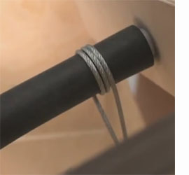
There you wrap the cable around the rubber casing three times and feed it further via the ring nut on the left of the steering unit down to the left-hand base plate where you feed it through the ring nut again towards the left-hand front wheel. Fix the turnbuckle under the base plate with another simplex clamp.
Connect the other end of the turnbuckle with a carabiner to the ring nut on the left-hand side of the front axle. Now you can tension the cable with the turnbuckle. For the brake, a control cable runs from each side of the pedal through the opening in the base and the ring nut to the brake rod.
Fix the cables to the ring nuts on the brake pedal with simplex clamps. Again add a turnbuckle at the back and fix it with a carabiner to the ring nut on the brake rod. To ensure that the brake releases, screw on a return spring from below for each brake between the brake rods and the rear axle with spacer rings and washers. When everything is connected, turn the turnbuckle to apply sufficient tension to the brake cable.
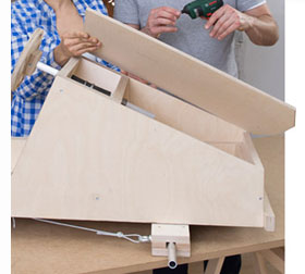
Fitting the body components
Now the bodywork of the soapbox car needs to be fitted. First of all, screw on the radiator and the first tail. Then fit the side sections. Now you can mount the bonnet on the side sections and the radiator. Then fit the second tail between the side sections (each with 3.5-x-30-mm screws). Finally, mount the spoiler and the bumpers with screws (3.5 x 40 mm).
Mounting the wheels and installing the seat
Before you can drive it, the soapbox car needs a seat and wheels. Each wheel is held in position by two shaft collars. Simply slide the first shaft collar onto the axle, then the wheel and then the second shaft collar. The shaft collars are locked with set screws.
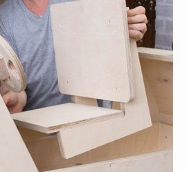
The seat consists of the seat frame, the backrest and the seat panel. Mark the contour and saw the components into shape with the jigsaw. Pre-drill holes through the seat frame (5 mm diameter), so that you can later mount the seat on the soapbox car, and screw the backrest to the seat frame. Then you can place the seat in the soapbox car. Once it is in the right position, screw it tight. Finally, fit the seat panel.
To be safe, now check all connections again. Then your soapbox car is ready to go.